14+ Refrigeration Cycle Ph Diagram
The enthalpy for the subcooled liquid of 20 o F is 1584 BtuLb from Figure 1-3. Web Representing Refrigeration Cycle on PH Diagram.

Pressure Enthalpy Diagram Of A Refrigeration Cycle With Performance Download Scientific Diagram
The reversed Carnot cycle is the most efficient refrigeration cycle operating between two specified temperature levels.
. A change of state occurs when the refrigerant flows through one of the four main components of the refrigeration plant. Web The Refrigeration Cycle Complete. 1 condenser 2 expansion valve 3 evaporator 4 compressor Note that this diagram is flipped vertically and horizontally compared to the previous one 6 Temperatureentropy diagram of the vapor-compression cycle.
Web The two red lines in the diagram are drawn to be straight drops for the intersection of the cycle point compressor inlet and compressor discharge. T-s diagram and major components for Carnot refrigerator. Web Here is how a Ph charts looks.
We define new concepts such as Entropy and Enthalpy and the use of the P-H diagram. Web Component diagram and P-h cycle of this refrigeration system is as shown in figure 14 and figure 15. Theoretical analysis of vapour refrigeration cycle with hybrid refrigerant of different types and mixing.
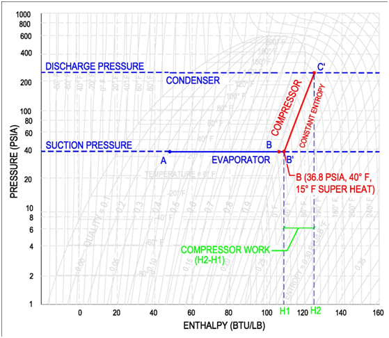
Web The following figure indicates the refrigeration cycle schematic with the above-mentioned processes which can be also represented in the log p-h diagram as shown in figure 1. In this final diagram of the refrigeration cycle we have introduced 3 new terms. From there well discuss each of the points in the PH diagram and see how they relate to the actual operation of air conditioners.
Web Refrigeration - Cycle for Ideal conditions on a Pressure Enthalpy Chart. Web For comparison a simple stylized diagram of a heat pumps vapor-compression refrigeration cycle. The coefficient of performance for Carnot refrigerators and heat pumps.
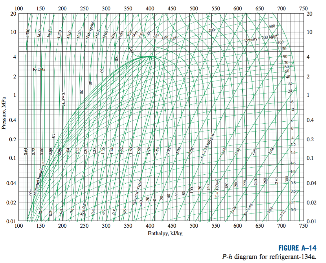
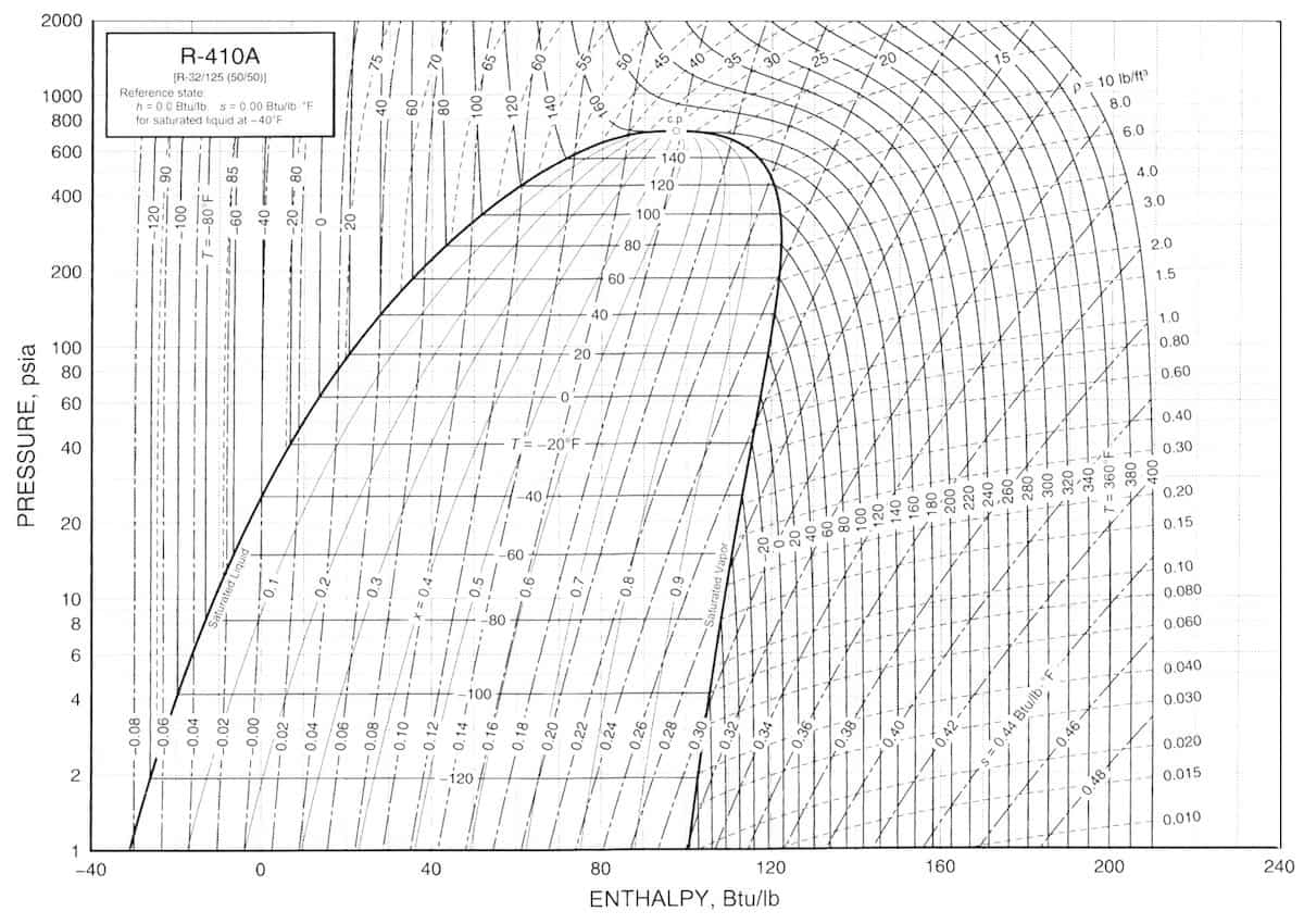
High Quality P-H Charts. Web The pressure-enthalpy diagram is the most common graphical tool for analysis and calculation of the heat and work transfer and performance of a refrigeration cycle. Web 89K views.
In this chapter we will discuss the basics of a refrigeration cycle mainly the vapor compression cycle main concept parts components working principle explained for HVAC system along with a real example etc. 191 Schematic of vapor-compression refrigeration cycle Full size image The efficiency with which a refrigerator or heat pump utilizes electricity to produce either cooling or heating is known as the coefficient of performance. Web P-H Diagram for Refrigeration System of Cogitation-2.
Refrigeration cycle is used to cool aircraft and to obtain. In this video we explain the importance of the P-H diagram and how useful this is for the refrigeration cycle. Web 3 Medium Quality P-H Charts 4 Related FAQ Refrigerants Pressure Enthalpy Charts The pressure-enthalpy diagram log Ph diagram is a very useful tool for refrigerant technicians engineers and researchers.
This ensures the refrigerant is in a gas state with no liquid present. Analyzing the PH Diagram. Web The P-h diagram is another convenient diagram often used to.
Web Compressor Evaporator QL QL Cold medium TL Fig. Web Log p-h diagram. The COP value is displayed above a schematic drawing of the mechanical.
Learn how to draw a cycle for ideal conditions on a PH chartPlease provide feedback on this module by selecting Like or. Since its not always possible to have all of these diagrams together we decided to give you this complete pack. Chapter 10-14 Absorption Refrigeration Systems Another form of refrigeration that becomes economically attractive when there is a source of inexpensive heat energy at a temperature of 100 to 200o.
Web So Ill explain the PH diagram for refrigeration in detail. The change in pressure can be clearly illustrated on the p-h diagram. The lines cross the enthalpy line at 1775 and 1885 approximately.
SUPERHEAT Is an amount of heat added to refrigerant vapour beyond its boiling point. The distinctive feature of the refrigeration cycle is that it runs counter-clockwise ie. Opposite to the joule or steam cycle.
In this post Ill go through the basics of a PH diagram and how to read it. Web 1 List the refrigerant characteristics that are shown on a pressure-enthalpy diagram PH. These thermodynamic processes form a closed cycle called the theoretical Linde circuit which is standard circuit for real compressor refrigeration systems.
The ET for the subcooler is -20 o F which is the same as the main evaporator. The Ph chart graphically shows where the physical states of these five mechanical components is and what is happening to the refrigerant within these components. Web Download scientific diagram P-h Diagram cycle of the refrigeration from publication.
Plotting the Vapor Compression Refrigeration Cycle on PH Diagram. Web Author found that reducing gas cooler porosity and outlet temperature by 34 and 36C increased the cycle coefficient of performance coefficient of performance enhancement factor and gas cooler. Web This Demonstration illustrates how to calculate the coefficient of performance COP of an ideal mechanical refrigeration system using a pressure-enthalpy diagram.
NRE H1 - H7 10242 1584 8658 BtuLb. Click the card to flip PH diagrams show the relationships between a refrigerants PRESSURE HEAT TEMPERATURE VOLUME and STATE. The NRE is extended to H7 instead of H6.
Gauge and absolute pressure is also explained. Web In this video we talk about the different processes associated with each component of the refrigeration cycle. Superheated Saturated subcooled.
Web The refrigeration cycle is the main basic cycle for all air conditioning and refrigeration equipment. It sets the highest theoretical COP. P-h diagram of VCR cycle 18 Diagram of components of domestic refrigerator18.
Use the sliders to set the enthalpies of the refrigerant at the four principal points in the cycle.

2 4 The Complex Cycle In A Log Ph Diagram Swep

Ideal Refrigeration Cycle P H Diagram 1 2 Isobaric Cooling And Download Scientific Diagram

Vapor Compression Refrigeration Cycle For R134a On P H Property Diagram Download Scientific Diagram

P H Diagram Cycle Of The Refrigeration Download Scientific Diagram
P H Diagram Thermodynamics Hvac And Refrigeration Pe Exam Tools Mechanical And Electrical Pe Sample Exams Technical Study Guides And Tools

Refrigeration Cycle For Ideal Conditions On A Pressure Enthalpy Chart Youtube

Simple Vapour Compression Refrigeration Cycle On P H Diagram Download Scientific Diagram

P H Diagrams Of A Typical Refrigeration Cycle And B Subcooled And Download Scientific Diagram
Solved An Ideal R 134a Vapor Refrigeration Cycle Operates Chegg Com

P H Diagram Showing The Refrigeration Cycle For An Air Conditioner With Download Scientific Diagram
Ph Diagram For Refrigeration Cycle In Depth Explanation Aircondlounge
Refrigeration Cycle Diagram Explained Refrigeration Hvac R Solar

Simple Vapour Compression Refrigeration Cycle On P H Diagram Download Scientific Diagram

P H Diagrams For Two Stage Refrigeration Cycle A Subcritical Cycle Download Scientific Diagram

Refrigeration Nonideal Refrigerant Conditions On A Pressure Enthalpy Chart Youtube
Refrigeration Cycle Diagram Explained Refrigeration Hvac R Solar

Refrigeration Schematic And A Pressure Enthalpy Chart Youtube